
5. Cortex M3
5장 Cortex-M3 개요
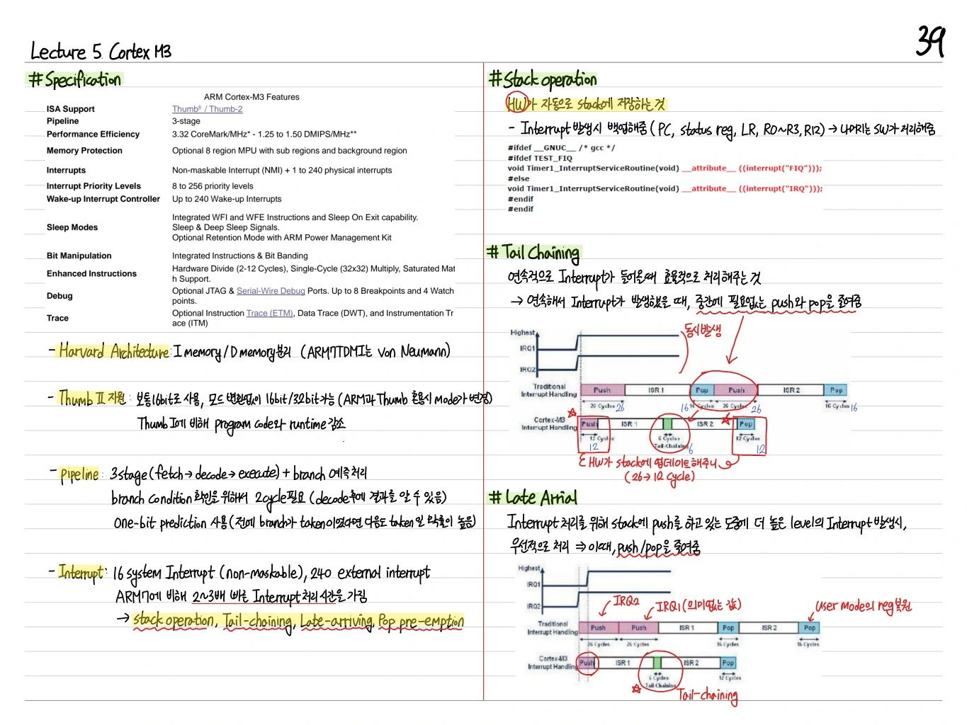
ARM Cortex-M3는 임베디드 마이크로컨트롤러를 위한 ARMv7-M 아키텍처 기반 프로세서다. Thumb-2 명령어 지원, 3-stage pipeline, NVIC(Nested Vectored Interrupt Controller), Memory-mapped bit-band 등을 특징으로 한다.
Specification
| 항목 | 값 |
|---|---|
| ISA Support | ARMv7-M (Thumb-2) |
| Pipeline | 3 stages (Fetch-Decode-Execute) |
| Performance Efficiency | 1.25 DMIPS/MHz |
| Memory Protection | Optional MPU |
| Interrupt Priority Levels | 3~256 |
| Instruction/Data Bus | Harvard architecture (separate I-bus, D-bus) |
| Sleep Modes | Integrated WFI, WFE, sleep-on-exit |
| Debug | Serial Wire / JTAG |
Harvard Modified Memory Architecture
Harvard: Instruction과 data를 별도 bus로 접근 — parallel access 가능, bandwidth 증가.
Pipeline (3-Stage)
Cortex-M3는 3-stage pipeline을 사용:
- Fetch: instruction을 메모리에서 가져옴
- Decode: instruction 해석, register 읽기 + branch prediction 수행
- Execute: ALU 연산, memory access, writeback
Branch 예측 실패 시 pipeline flush → stall 발생. Late arrival: 다음 I가 branch 결과를 기다리는 경우.
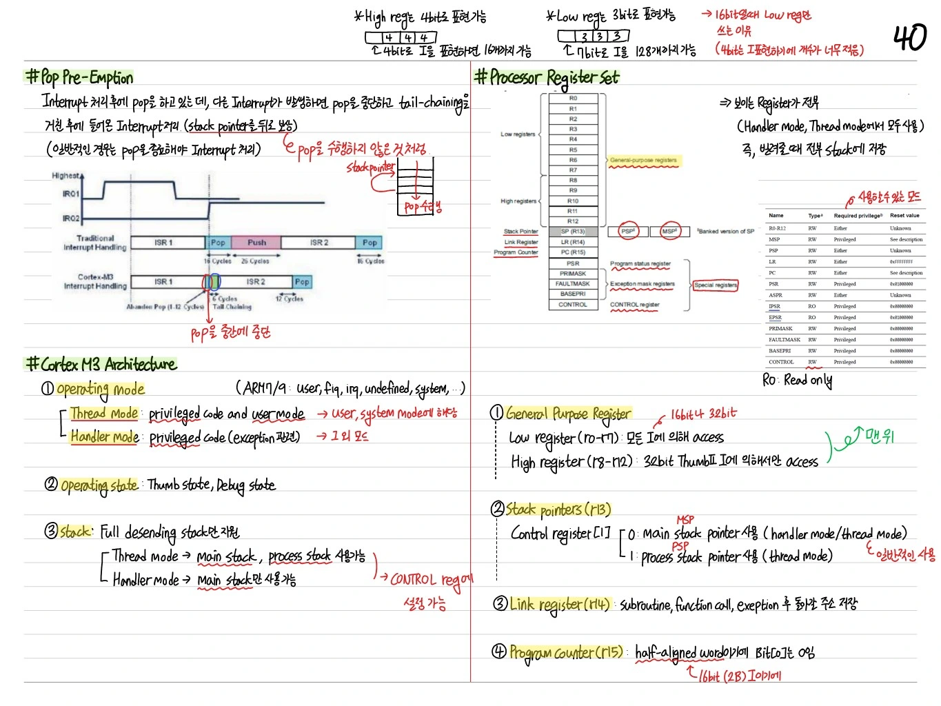
Cortex-M3 Architecture
- Operating Mode: Thread mode, Handler mode
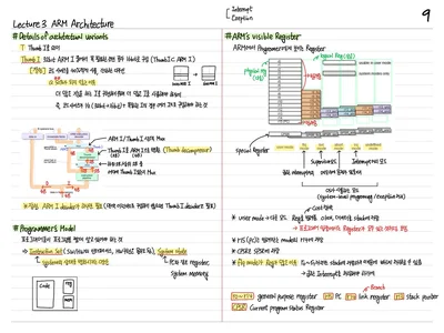
- Processor Register Set: R0~R12 (general), R13 (SP), R14 (LR), R15 (PC), xPSR
- Bank stacks: MSP (Main Stack Pointer) — OS/exception, PSP (Process Stack Pointer) — user thread
General Purpose Register (R0~R12)
- Low registers (R0~R7): 16-bit Thumb I에서 직접 사용
- High registers (R8~R12): 대부분 32-bit Thumb-2 I에서만 직접 사용
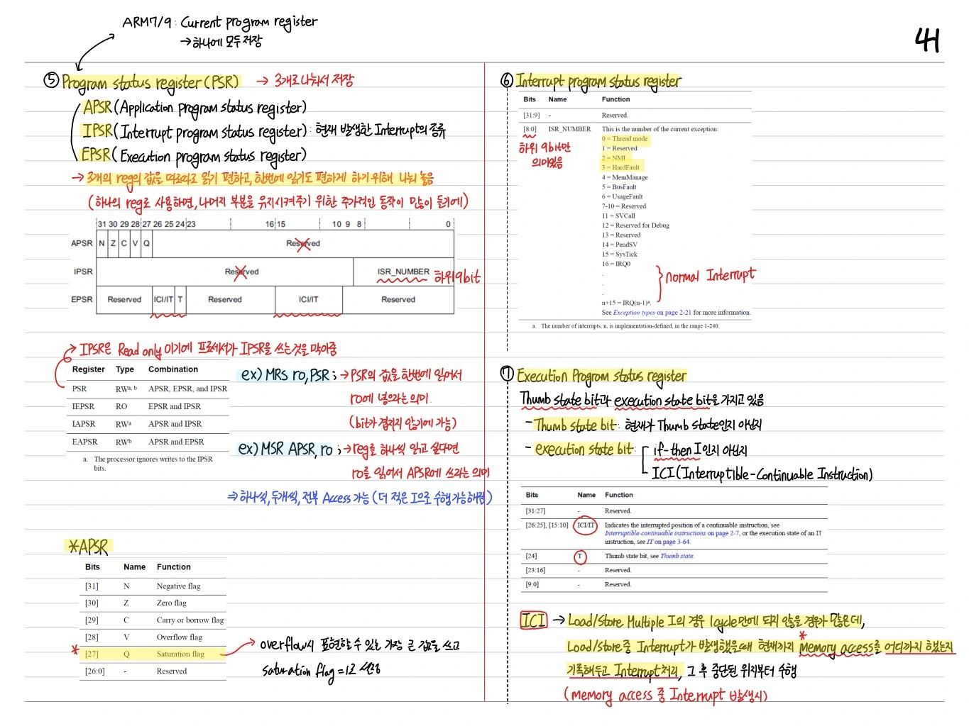
Program Status Register (xPSR)
ARMv7-M은 xPSR을 세 부분으로 접근:
- APSR: N, Z, C, V, Q flags
- IPSR: 현재 실행 중인 exception 번호
- EPSR: Thumb state bit, IT block state, ICI bits
APSR Flags
- N(bit 31): Negative, Z(bit 30): Zero, C(bit 29): Carry, V(bit 28): Overflow, Q(bit 27): Sticky saturation
IPSR
- bits[8:0]: 현재 exception number. Thread mode에서 0.
EPSR
- Thumb bit: Cortex-M은 Thumb mode만 지원 → 항상 1
- IT bit: IT (If-Then) block의 conditional execution 상태
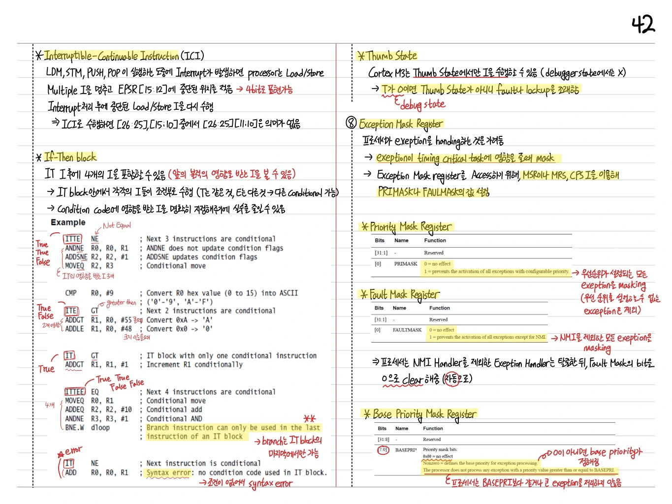
Special Purpose Registers
PRIMASK
1-bit flag. 1이면 configurable exception mask (NMI와 HardFault는 예외).
FAULTMASK
1-bit flag. 1이면 NMI 제외한 모든 exception masking.
BASEPRI
8-bit priority. 이 값보다 낮은 우선순위의 interrupt를 mask.
CONTROL
- SPSEL (bit 0): active stack pointer (0=MSP, 1=PSP)
- nPRIV (bit 1): privileged level (0=privileged, 1=unprivileged)
IT (If-Then) Block
Thumb-2의 Conditional Execution. IT 명령어 뒤에 최대 4개의 conditional I를 배치:
CMP r0, r1
ITTE  EQ
MOVEQ r2, r3
ADDEQ r4, r4, #1
MOVNE r5, r6
→ Branch 없이 조건부 실행 → pipeline 효율 ↑.
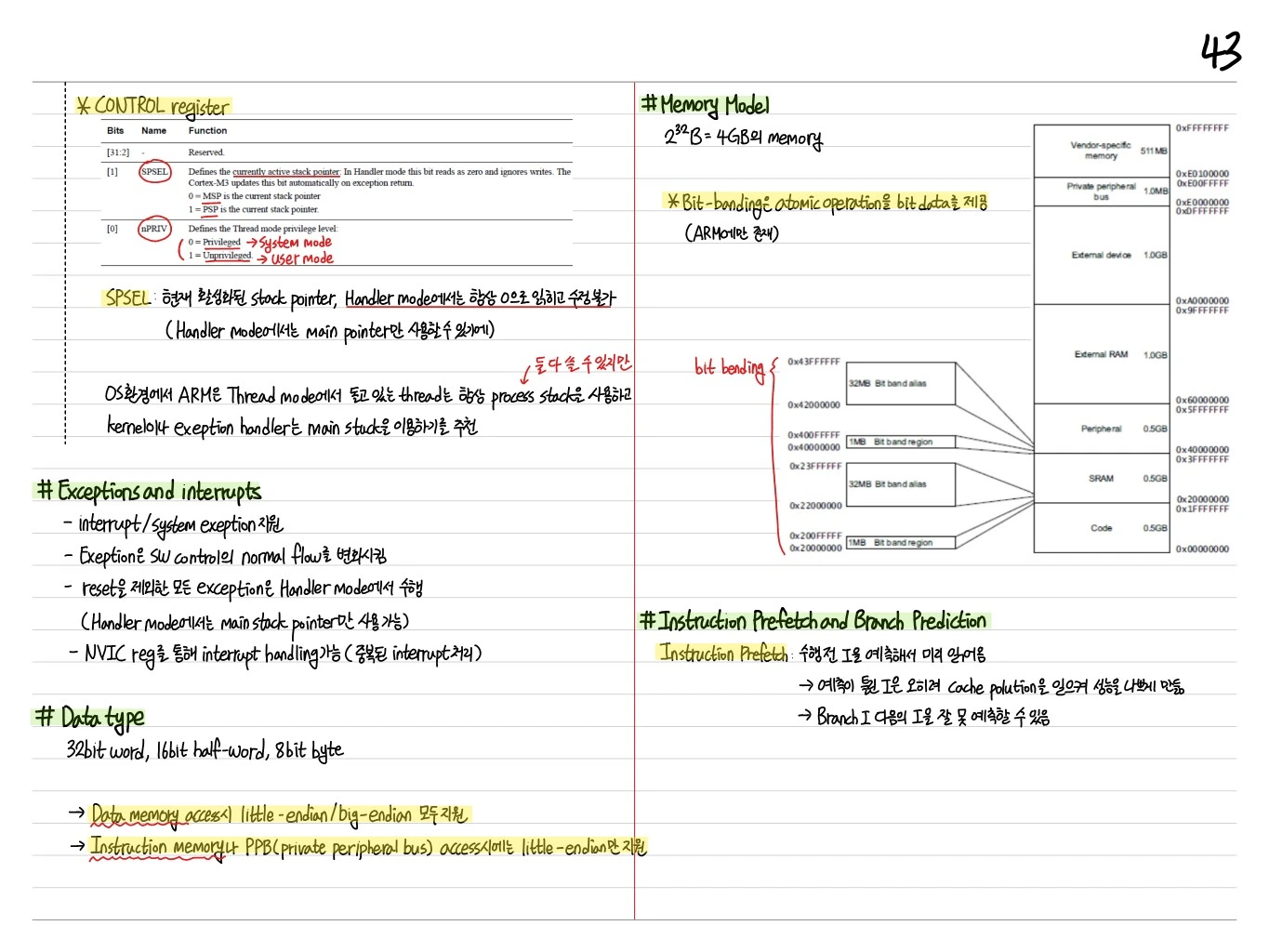
CONTROL Register 상세
| Bits | Name | Function |
|---|---|---|
| [31:2] | Reserved | - |
| [1] | SPSEL | Active stack pointer (0=MSP, 1=PSP). Handler mode: 항상 0 |
| [0] | nPRIV | Thread mode privilege (0=Privileged, 1=Unprivileged) |
- SPSEL: 현재 활성화된 stack pointer. Handler mode에서는 항상 0으로 읽히고 수정 불가
- OS 환경에서 ARM은 Thread mode의 thread는 항상 process stack, kernel/exception handler는 main stack 이용을 추천
Exceptions and Interrupts
- Interrupt/system exception 지원
- Exception은 SW control의 normal flow를 변화시킴
- Reset을 제외한 모든 exception은 Handler mode에서 수행
- NVIC reg를 통해 interrupt handling 가능 (중복된 interrupt 처리)
Data Type
- 32-bit word, 16-bit half-word, 8-bit byte
- Data memory access: little-endian/big-endian 모두 지원
- Instruction memory, PPB access: little-endian만 지원
Memory Model
$2^{32}$ B = 4 GB의 memory.
0xFFFFFFFF  Vendor-specific (511 MB)
0xE0100000
0xE00FFFFF  Private peripheral bus (1.0 MB)
0xE0000000
0xDFFFFFFF  External device (1.0 GB)
0xA0000000
0x9FFFFFFF  External RAM (1.0 GB)
0x60000000
0x5FFFFFFF  Peripheral (0.5 GB)  — bit-banding region
0x40000000
0x3FFFFFFF  SRAM (0.5 GB)  — bit-banding region
0x20000000
0x1FFFFFFF  Code (0.5 GB)
0x00000000
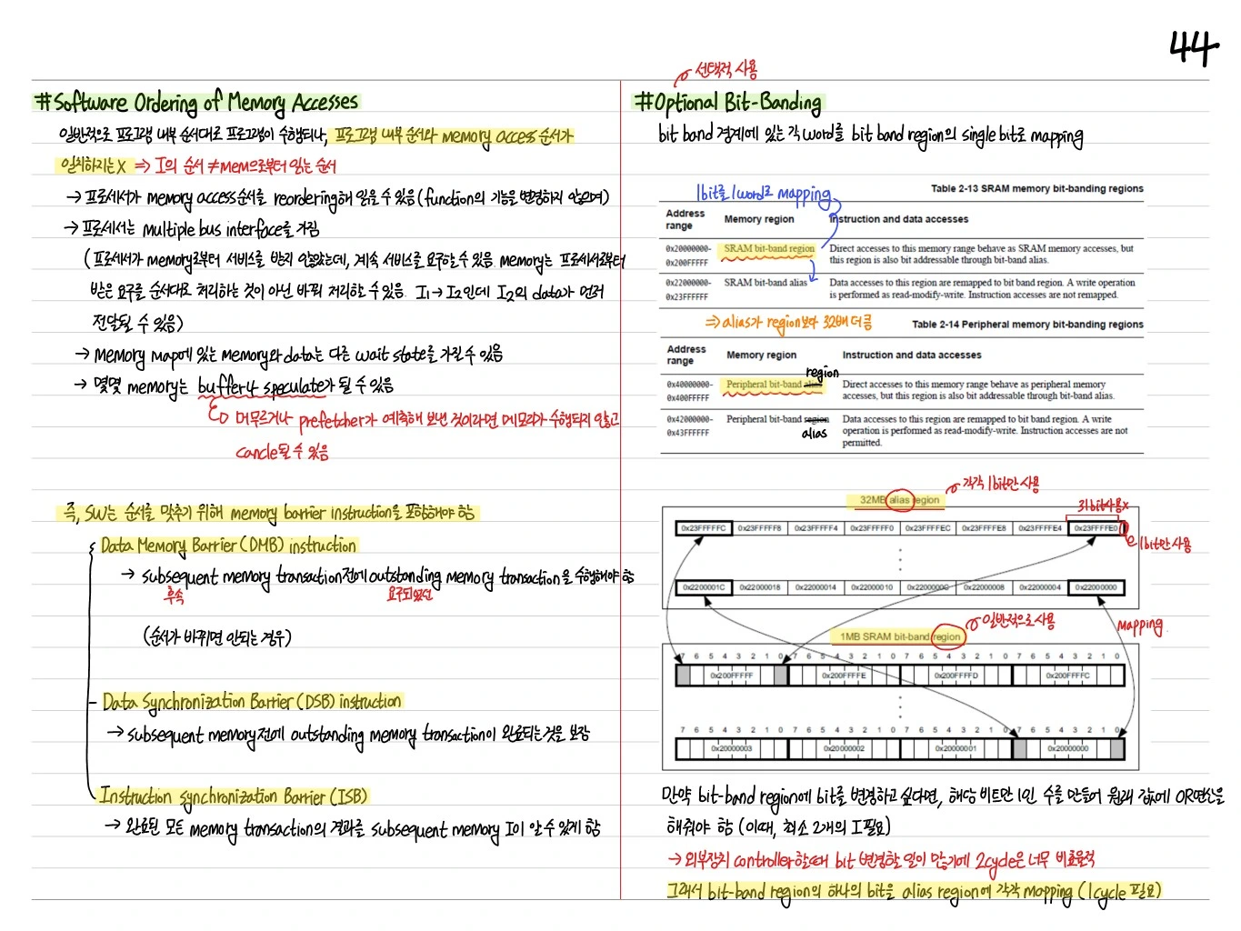
Bit-Banding
Cortex-M3의 특징: Atomic operation을 bit data로 제공 (ARM에만 존재).
- Peripheral 0.5GB / SRAM 0.5GB region에서 1MB Bit band region → 32MB Bit band alias
- Alias의 한 word(32-bit)는 bit-band region의 한 bit에 대응
- Alias 주소에 read/write하면 해당 bit만 atomic하게 read/modify 가능
Instruction Prefetch and Branch Prediction
Instruction Prefetch: 수행 전 I을 예측해서 미리 읽어둠.
- 예측이 틀린 I은 cache pollution을 일으켜 성능 저하
- Branch I 다음의 I을 잘 못 예측할 수 있음
Software Ordering of Memory Access
- DMB (Data Memory Barrier): 이전 memory access 완료 후 이후 access
- DSB (Data Synchronization Barrier): DMB + instruction 완료까지 보장
- ISB (Instruction Synchronization Barrier): Pipeline flush
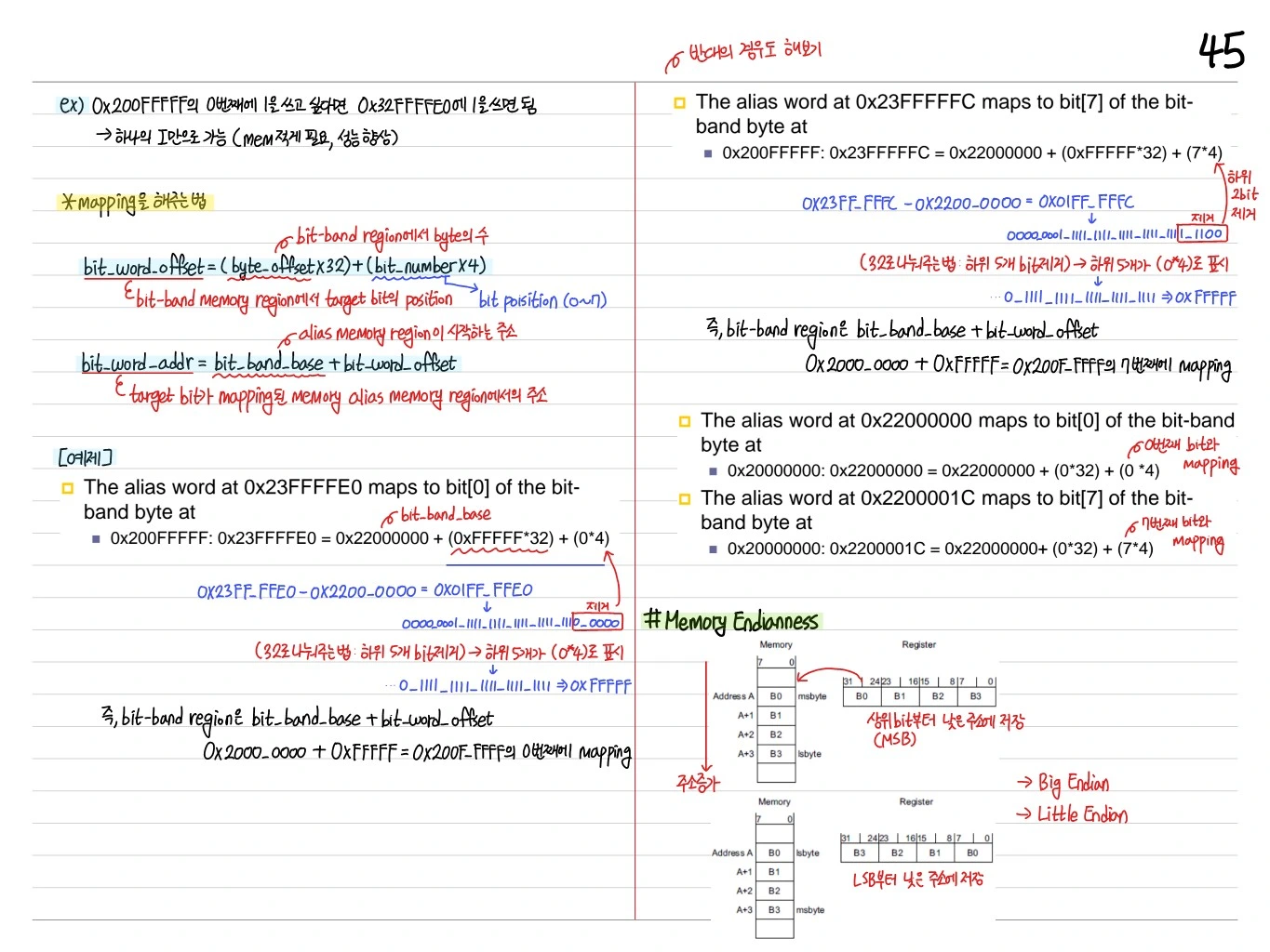
Bit-Banding 주소 변환
bit_word_offset = (byte_offset x 32) + (bit_number x 4)
bit_word_addr = bit_band_base + bit_word_offset
예: SRAM bit-band region 0x20000000 → alias 0x22000000
- 0x20000000 bit 0 → 0x22000000
- 0x20000000 bit 1 → 0x22000004
- 0x20000000 bit 2 → 0x22000008
Memory Endianness
- Big Endian / Little Endian 선택 가능
- Cortex-M3의 code fetch는 항상 little-endian
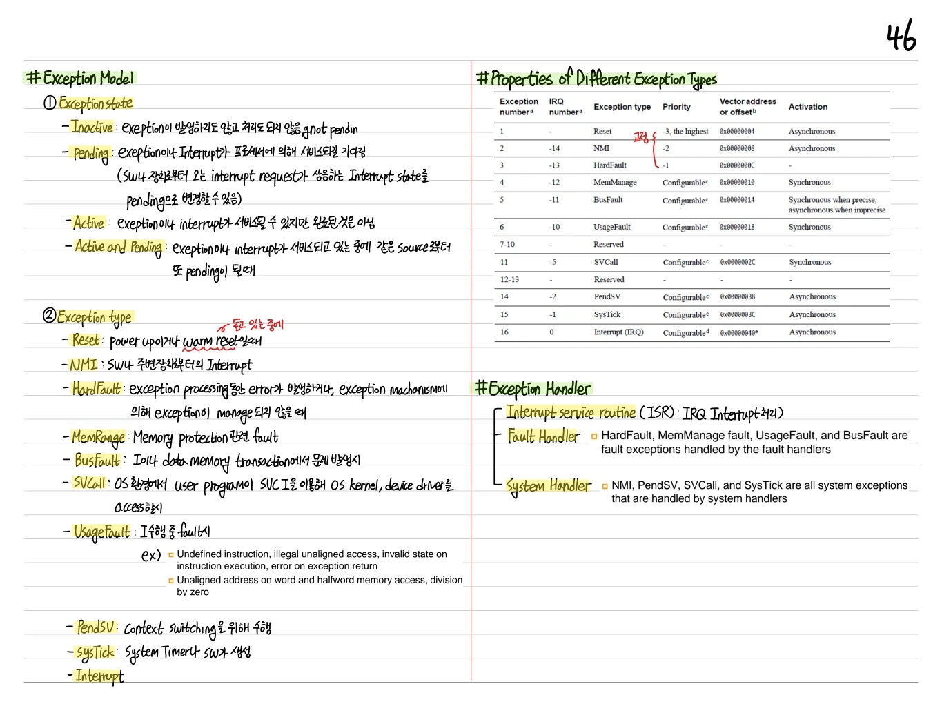
Exception Model
Cortex-M3의 Exception 체계. Reset, NMI, HardFault, MemManage, BusFault, UsageFault, SVCall, DebugMonitor, PendSV, SysTick, IRQ[0..239].
Exception Type (우선순위 순)
- Reset: 가장 높음 (fixed)
- NMI: 2번째 (fixed)
- HardFault: fault escalation
- Configurable: MemManage, BusFault, UsageFault, SVCall, DebugMonitor, PendSV, SysTick, IRQ
- IRQ: 외부 peripheral
Exception Handlers
- ISR (Interrupt service routine): IRQ handler
- Fault handler: HardFault, MemManage, UsageFault, BusFault
- System handler: NMI, PendSV, SVCall, SysTick
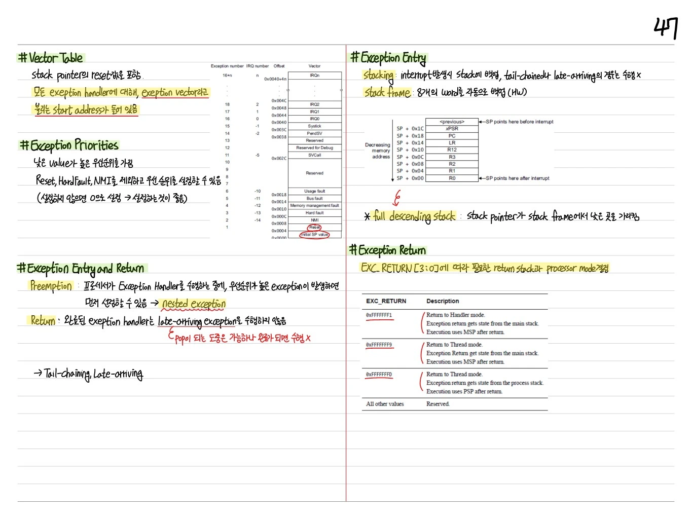
Vector Table
Stack pointer의 reset값을 포함. 모든 exception handler의 start address가 들어 있음.
| Exception number | IRQ number | Offset | Vector |
|---|---|---|---|
| 16+n | n | 0x0040+4n | IRQn |
| 15 | -1 | 0x003C | SysTick |
| 14 | -2 | 0x0038 | PendSV |
| 11 | -5 | 0x002C | SVCall |
| 6 | -10 | 0x0018 | Usage fault |
| 5 | -11 | 0x0014 | Bus fault |
| 4 | -12 | 0x0010 | Memory management fault |
| 3 | -13 | 0x000C | Hard fault |
| 2 | -14 | 0x0008 | NMI |
| 1 | - | 0x0004 | Reset |
| 0 | - | 0x0000 | Initial SP value |
Exception Priorities
낮은 value가 높은 우선순위.
- Reset, HardFault, NMI를 제외하고 우선 순위를 설정할 수 있음
- 설정하지 않으면 0 → 설정하는 것이 좋음
Exception Entry and Return
Preemption
프로세서가 Exception Handler를 수행하는 중, 우선순위가 높은 exception이 발생하면 선점 → Nested exception.
Return
완료된 exception handler는 late-arriving exception을 수행하지 않음. Pop 도중은 가능하나 완료 되면 수행 X.
→ Tail-chaining, Late-arriving 최적화.
Exception Entry — Stacking
- Stacking: Interrupt 발생 시 stack에 백업, tail-chained나 late-arriving은 수행 X
- Stack frame: 8개의 word 자동 백업 (HW)
SP + 0x1C    <previous>
SP + 0x18    xPSR
SP + 0x14    PC
SP + 0x10    LR
SP + 0x0C    R12
SP + 0x08    R3
SP + 0x04    R2
SP + 0x00    R1, R0
Full descending stack: Stack pointer가 stack frame의 낮은 곳.
Exception Return
EXC_RETURN[3:0] 값에 따라 return stack과 processor mode 결정.
| EXC_RETURN | Description |
|---|---|
| 0xFFFFFFF1 | Return to Handler mode. State from MSP. Execution uses MSP. |
| 0xFFFFFFF9 | Return to Thread mode. State from MSP. Execution uses MSP. |
| 0xFFFFFFFD | Return to Thread mode. State from PSP. Execution uses PSP. |
정리
| 요소 | 설명 |
|---|---|
| ARMv7-M, Thumb-2 | 16/32-bit 혼용 instruction |
| 3-stage pipeline | Fetch-Decode-Execute + branch prediction |
| Harvard arch | I-bus, D-bus 분리 |
| MSP / PSP | OS/thread용 stack pointer 분리 |
| xPSR = APSR+IPSR+EPSR | Flag, exception 번호, Thumb/IT 상태 |
| Bit-banding | Atomic bit access via alias address |
| NVIC + Tail-chaining | 저지연 nested interrupt |
| Memory barrier | DMB/DSB/ISB로 multi-master 동기화 |
Cortex-M3는 저전력 임베디드 MCU 시장(STM32, LPC17xx 등)의 표준이 되었고, 이후 Cortex-M4, M7로 확장된다.
 Embedded Note
 AI Study Note
 SoC Note
Comments (0)
No comments yet. Be the first to comment!
Please to write a comment.