
8. Hardware Hacking
8장 Hardware Hacking 개요
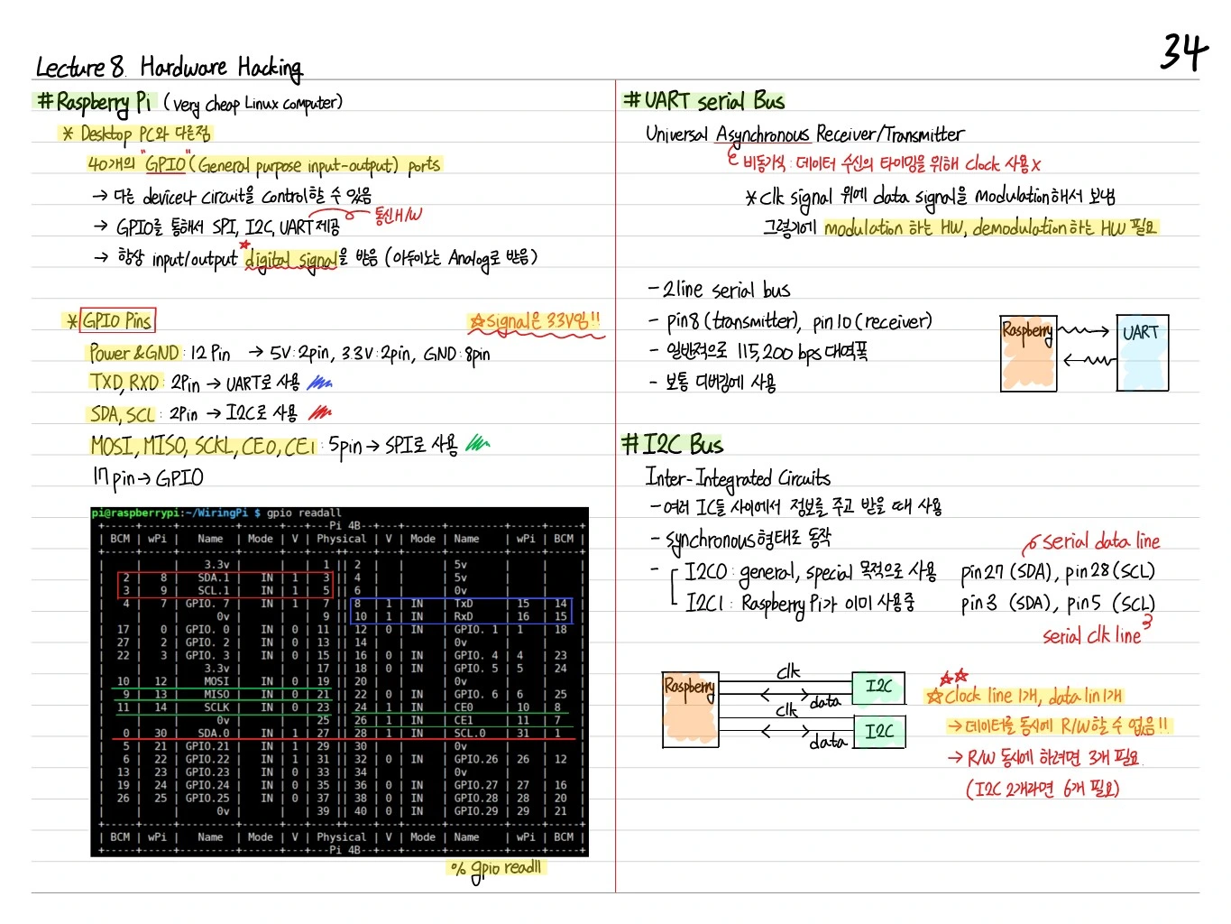
Raspberry Pi에 GPIO, UART, I2C, SPI를 이용해 외부 device를 직접 제어하는 방법과, BCM2835 Peripheral Register를 직접 조작하여 LED를 켜는 실습까지 다룬다.
Raspberry Pi (+ Linux computer)
- Raspberry Pi는 GPIO, UART, SPI, I2C 등 여러 serial/parallel I/O 인터페이스를 지원
- Linux 기반이므로 shell에서 쉽게 접근 가능
GPIO (General Purpose I/O)
- Digital I/O pins: 외부 device와 control, detect signals 주고받음
- 각 pin: VCC, GND, 혹은 logic signal (3.3V, logic-level)
- 3.3V reference voltage
UART serial (Universal Asynchronous Receiver/Transmitter)
- 2 wire signal line, asynchronous transmission: $t_r$, $t_s$
- TX (Transmit): PC → UART
- RX (Receive): UART → PC
- 기본 serial bus
- TX (transmitter): 데이터 전송
- RX (receiver): 데이터 수신
- 기본 UART setup 필요
I2C Bus (Inter-Integrated Circuits)
- SDA (Serial Data Line)
- SCL (Serial Clock Line)
- 2 wire bus
- Master-Slave 구조, 여러 slave device 연결 가능
- I2C-1: Raspberry Pi에서 사용 (기본 /dev/i2c-1)
SPI Bus — Serial Peripheral Interface
Synchronous bus, 4 wires
- MOSI (Master Out Slave In): SPI master output, slave input
- MISO (Master In Slave Out): SPI master input, slave output
- SCLK: Serial Clock
- SS/CE (Slave Select / Chip Enable): SPI slave를 선택
Limitations of Raspberry Pi using GPIO
- 총 wire의 수를 신경 써야 함 → Raspberry Pi 기준 총 26 or 40 pin
- 각 pin 간 타이밍/전기적 특성도 고려
wiringPi
- WiringPi: C 라이브러리, GPIO control
- Command line:
gpio readall등 편리한 명령어 제공
LED Circuit
- LED는 3.3V나 5V로 동작
- 저항(resistor, 220~330Ω)을 직렬 연결해 current limiting
- GPIO pin을 High로 하면 LED ON, Low로 하면 OFF
Makefile
LEDs: LEDs.c
    gcc -Wall -o LEDs LEDs.c -l wiringPi
BCM2835 ARM Peripherals
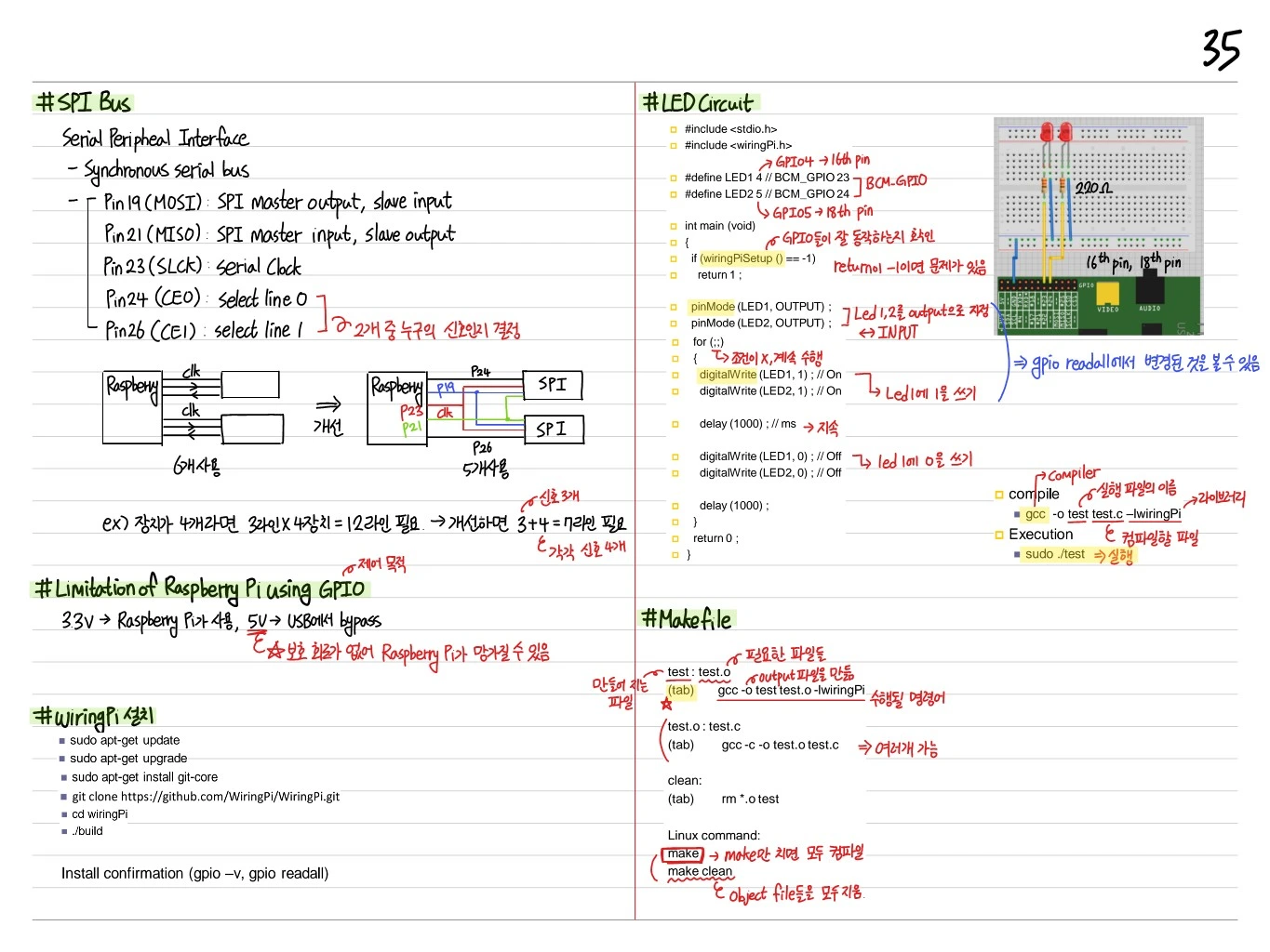
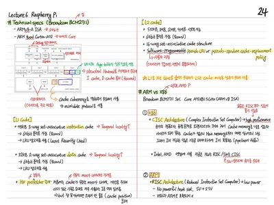
Broadcom BCM2835(Raspberry Pi의 SoC)의 peripheral register 구조:
- Peripheral addressing: Physical Address (PA)가 특정 offset에서 peripheral register에 매핑됨
- ARM Physical Address: 0x00000000 ~ 0xFFFFFFFF 중 peripheral 영역은 0x20000000대
GPIO Bus Address Layout
- BCM2835: GPIO base =
0x20200000(Raspberry Pi 1) /0x3F200000(Raspberry Pi 2/3) - GPIO의 각 기능 register가 offset 기준으로 배치됨
Register View
| Address | Register | Description |
|---|---|---|
| 0x20200000 | GPFSEL0 | Function Select pins 0-9 |
| 0x20200004 | GPFSEL1 | Function Select pins 10-19 |
| 0x20200020 | GPSET0 | Pin Output Set 0 |
| 0x2020002C | GPCLR0 | Pin Output Clear 0 |
| ... | ... | ... |
- GPFSEL: Pin function (input/output/alternate)
- GPSET: Set pin HIGH
- GPCLR: Clear pin to LOW
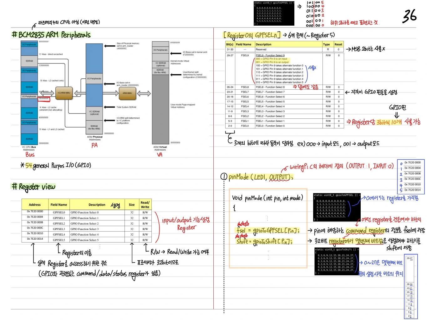
Register Map (GPFSEL x)
각 GPFSEL register는 10개 pin × 3 bits = 30 bits를 사용해 function을 설정.
- 000 = Input
- 001 = Output
- 010~111 = Alternate function (UART, I2C, SPI 등)
pinMode Function
void pinMode(uint8_t pin, uint8_t mode) {
    uint8_t gpfsel = pin / 10;
    uint8_t offset = (pin % 10) * 3;
    uint32_t mask = 0b111 << offset;
    *(gpio + gpfsel) = (*(gpio + gpfsel) & ~mask) | (mode << offset);
}
예: pin 4를 output으로 설정하려면 GPFSEL0의 bit[14:12]를 001로.
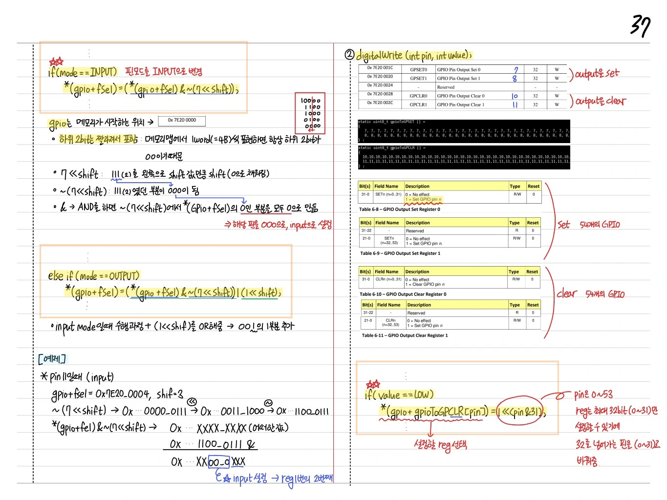
digitalWrite Function — 예제
if (value == HIGH)
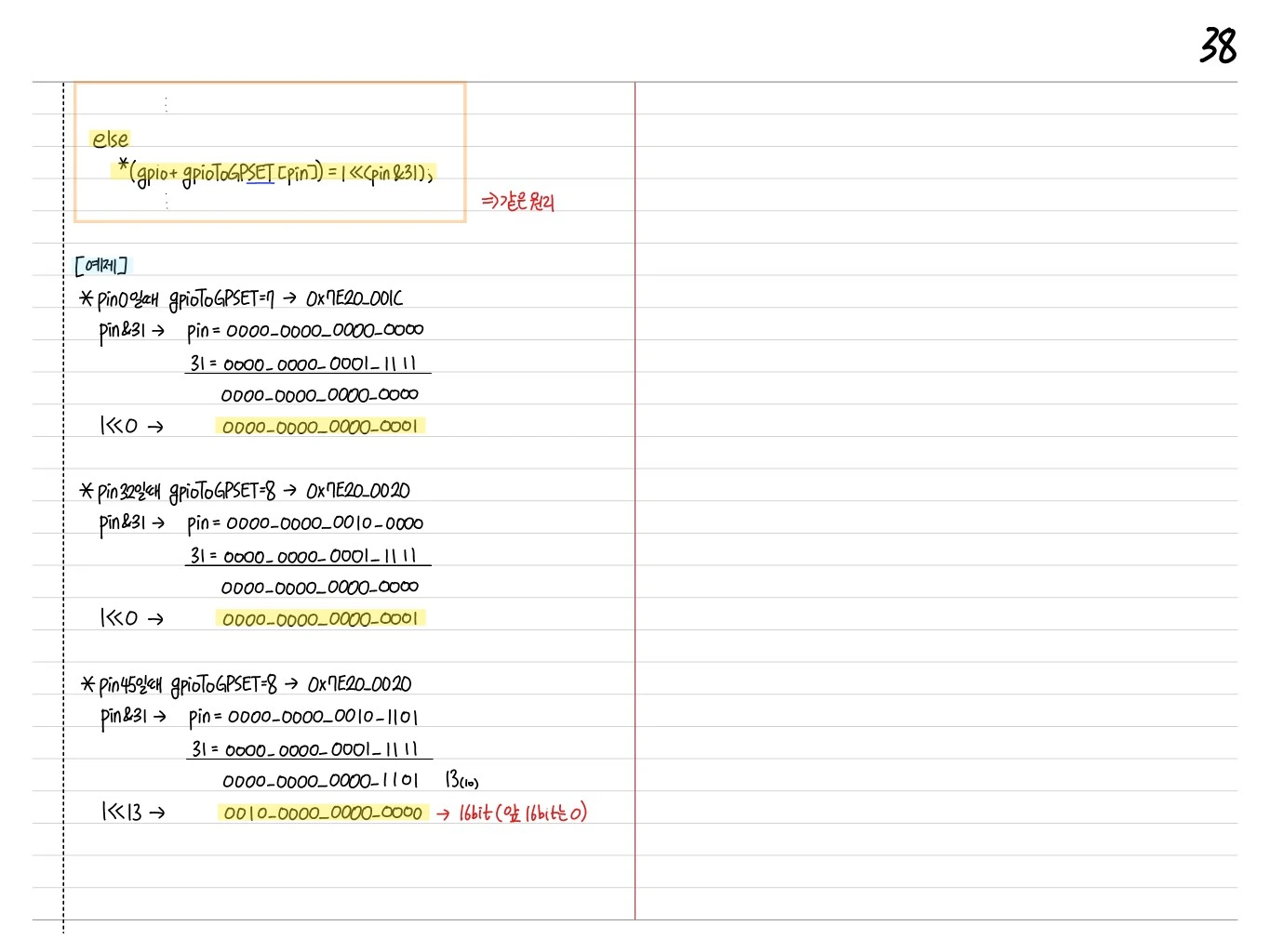
    *(gpio + gpioToGPSET[pin]) = 1 << (pin & 31);
else
    *(gpio + gpioToGPCLR[pin]) = 1 << (pin & 31);
같은 원리로 구현 (GPSET/GPCLR는 비슷).
예제: Pin에 따른 값 계산
- Pin 0일 때 gpioToGPSET = 7 → 0x7E20_001C
pin & 31→pin <mark class="highlight"><strong><u> 0000_0000_0000_0000,31 </u></strong></mark> 0000_0000_0001_1111→ AND =0000_0000_0000_00001 << 0→0000_0000_0000_0001
- Pin 32일 때 gpioToGPSET = 8 → 0x7E20_0020
pin & 31:pin <mark class="highlight"><strong><u> 0000_0000_0010_0000,31 </u></strong></mark> 0000_0000_0001_1111→ AND =0000_0000_0000_00001 << 0→0000_0000_0000_0001
- Pin 45일 때 gpioToGPSET = 8 → 0x7E20_0020
pin & 31:pin <mark class="highlight"><strong><u> 0000_0000_0010_1101,31 </u></strong></mark> 0000_0000_0001_1111→ AND0000_0000_0000_110113 (10진수)1 << 13→0010_0000_0000_0000(16-bit, 앞 16 bit는 0)
정리
| 인터페이스 | 핵심 |
|---|---|
| GPIO | Digital I/O, 3.3V reference, 40 pin |
| UART | 비동기 2 wire (TX/RX) |
| I2C | 2 wire (SDA/SCL), master-slave |
| SPI | 4 wire (MOSI, MISO, SCLK, SS), high-speed |
| BCM2835 | Peripheral register를 메모리 매핑 |
| GPFSEL / GPSET / GPCLR | pin function, set high, clear |
Raspberry Pi의 GPIO를 HW 레벨에서 직접 제어하는 경험은 이후 임베디드 SoC (Cortex-M3, STM32) 작업의 기반이 된다.
 Embedded Note
 AI Study Note
 SoC Note
Comments (0)
No comments yet. Be the first to comment!
Please to write a comment.