
9. SoC Prgraming using C
9장 SoC Programming using C 개요
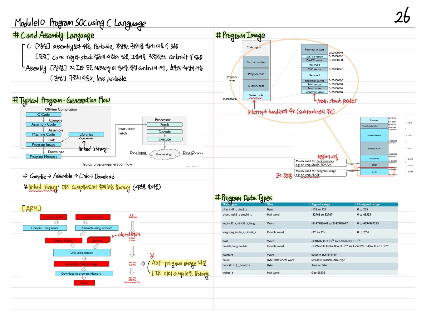
임베디드 SoC 프로그래밍을 C 언어로 수행하는 기본 방식. Memory-mapped I/O를 통한 peripheral 접근, pointer manipulation, volatile keyword, bit operation, startup sequence, linker script 등을 다룬다.
Memory-Mapped I/O
ARM Cortex-M에서는 모든 peripheral이 특정 메모리 주소에 매핑되어 있음. Register에 접근 = 해당 주소에 read/write.
#define GPIO_ODR (*(volatile uint32_t *)0x40020014)

GPIO_ODR = 0x01;   // GPIO 출력 설정
uint32_t val = GPIO_ODR;  // 현재 상태 읽기
volatile Keyword
- Compiler 최적화 방지 (예: 같은 주소를 두 번 읽을 때 생략 금지)
- Hardware register는 외부에서 바뀔 수 있으므로 반드시 volatile
volatile uint32_t *GPIO_IDR = (volatile uint32_t *)0x40020010;
while (!(*GPIO_IDR & 0x1)) ;  // 버튼 눌릴 때까지 대기
volatile이 없으면 compiler가 loop 최적화로 무한 대기 발생.
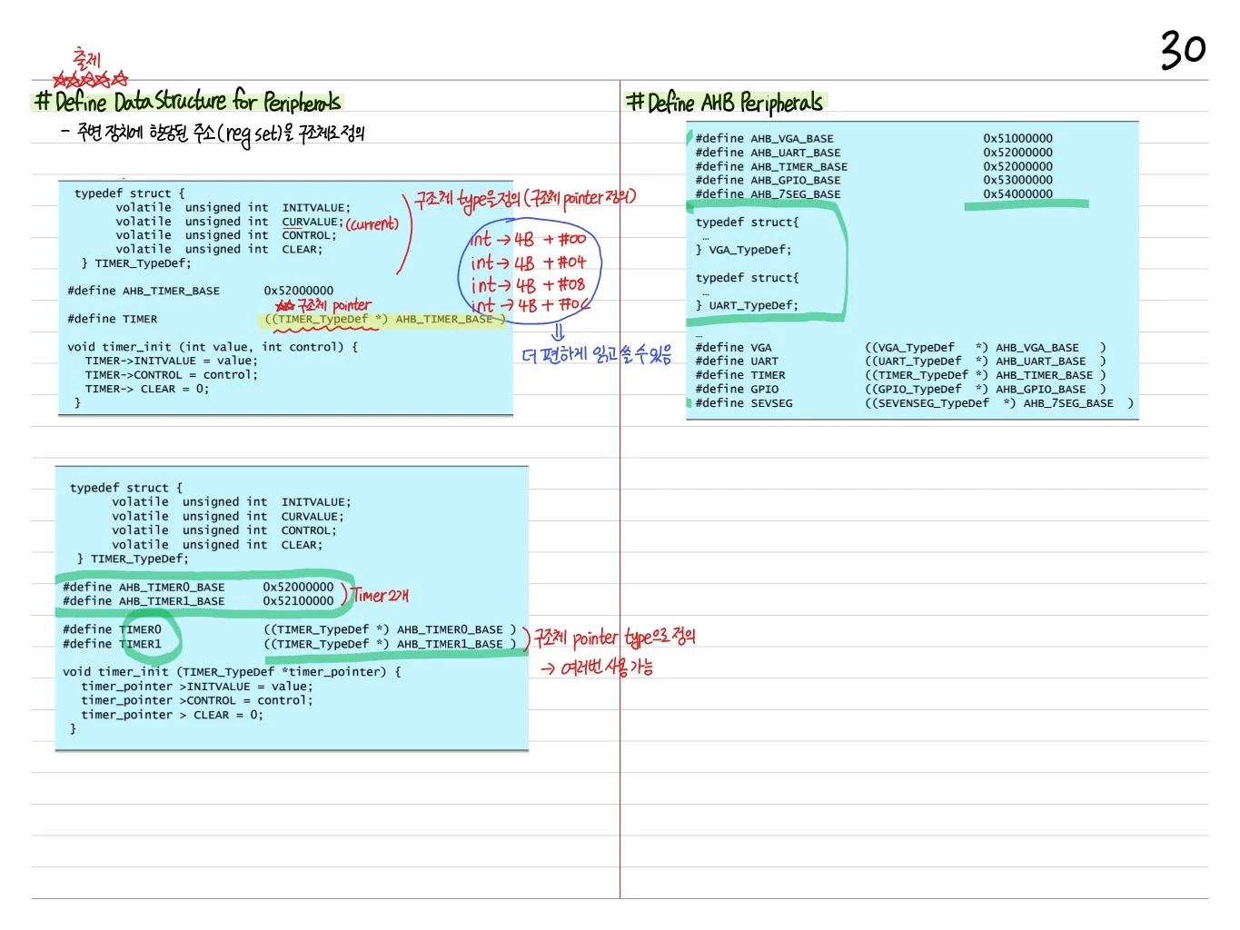
Struct 기반 Register 접근
대규모 peripheral은 struct로 정의 (CMSIS style):
typedef struct {
    volatile uint32_t MODER;    // 0x00
    volatile uint32_t OTYPER;   // 0x04
    volatile uint32_t OSPEEDR;  // 0x08
    volatile uint32_t PUPDR;    // 0x0C
    volatile uint32_t IDR;      // 0x10
    volatile uint32_t ODR;      // 0x14
    // ...
} GPIO_TypeDef;

#define GPIOA ((GPIO_TypeDef *)0x40020000)

GPIOA->ODR = 0x01;
Bit Operation
Bit Set
GPIOA->ODR |= (1 << 5); // 5번 bit를 1로
Bit Clear
GPIOA->ODR &= ~(1 << 5); // 5번 bit를 0으로
Bit Toggle
GPIOA->ODR ^= (1 << 5); // 5번 bit 반전
Bit Check
if (GPIOA->IDR & (1 << 5)) { /* bit 5 is 1 */ }
Multi-bit Field
2-bit field를 값 val로 설정:
GPIOA->MODER &= ~(0x3 << (pin * 2));    // clear 2 bits
GPIOA->MODER |= (val << (pin * 2));     // set value
Startup Sequence
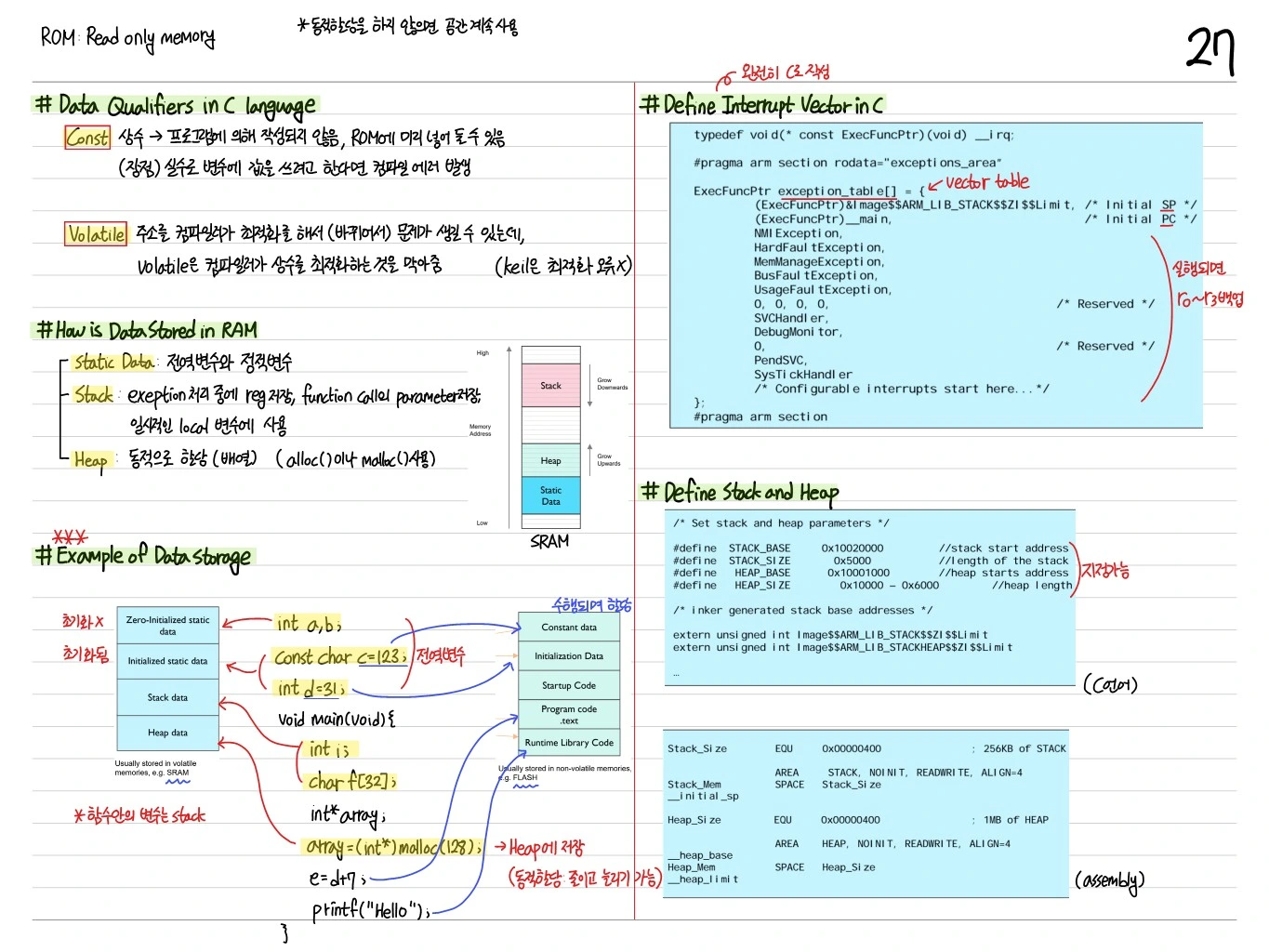
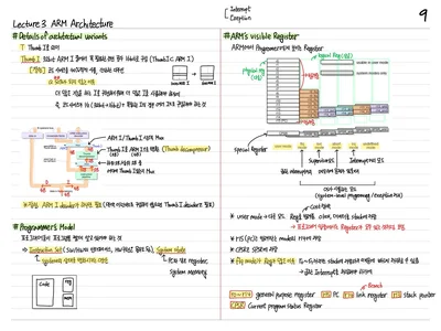
Reset 시 프로세서가 수행하는 초기화:
- R13 ← Initial SP (Vector table offset 0x00)
- PC ← Reset handler (offset 0x04)
- Reset handler:
-
.datasection을 Flash에서 RAM으로 copy -.bsssection을 0으로 초기화 -SystemInit()호출 (clock, PLL 설정) -main()호출
void Reset_Handler(void) {
    // Copy .data from Flash to RAM
    extern uint32_t _sdata, _edata, _sidata;
    uint32_t *src = &_sidata;
    uint32_t *dst = &_sdata;
    while (dst < &_edata) *dst++ = *src++;

    // Zero-init .bss
    extern uint32_t _sbss, _ebss;
    dst = &_sbss;
    while (dst < &_ebss) *dst++ = 0;

    SystemInit();
    main();
    while(1);
}
Linker Script
Memory layout 정의:
MEMORY {
    FLASH (rx) : ORIGIN <mark class="highlight"><strong><u> 0x08000000, LENGTH </u></strong></mark> 128K
    RAM (rwx)  : ORIGIN <mark class="highlight"><strong><u> 0x20000000, LENGTH </u></strong></mark> 20K
}

SECTIONS {
    .isr_vector : {
        KEEP(*(.isr_vector))
    } > FLASH

    .text : {
        *(.text*)
        *(.rodata*)
    } > FLASH

    .data : AT(_sidata) {
        _sdata = .;
        *(.data*)
        _edata = .;
    } > RAM

    .bss : {
        _sbss = .;
        *(.bss*)
        _ebss = .;
    } > RAM
}
CMSIS (Cortex Microcontroller Software Interface Standard)
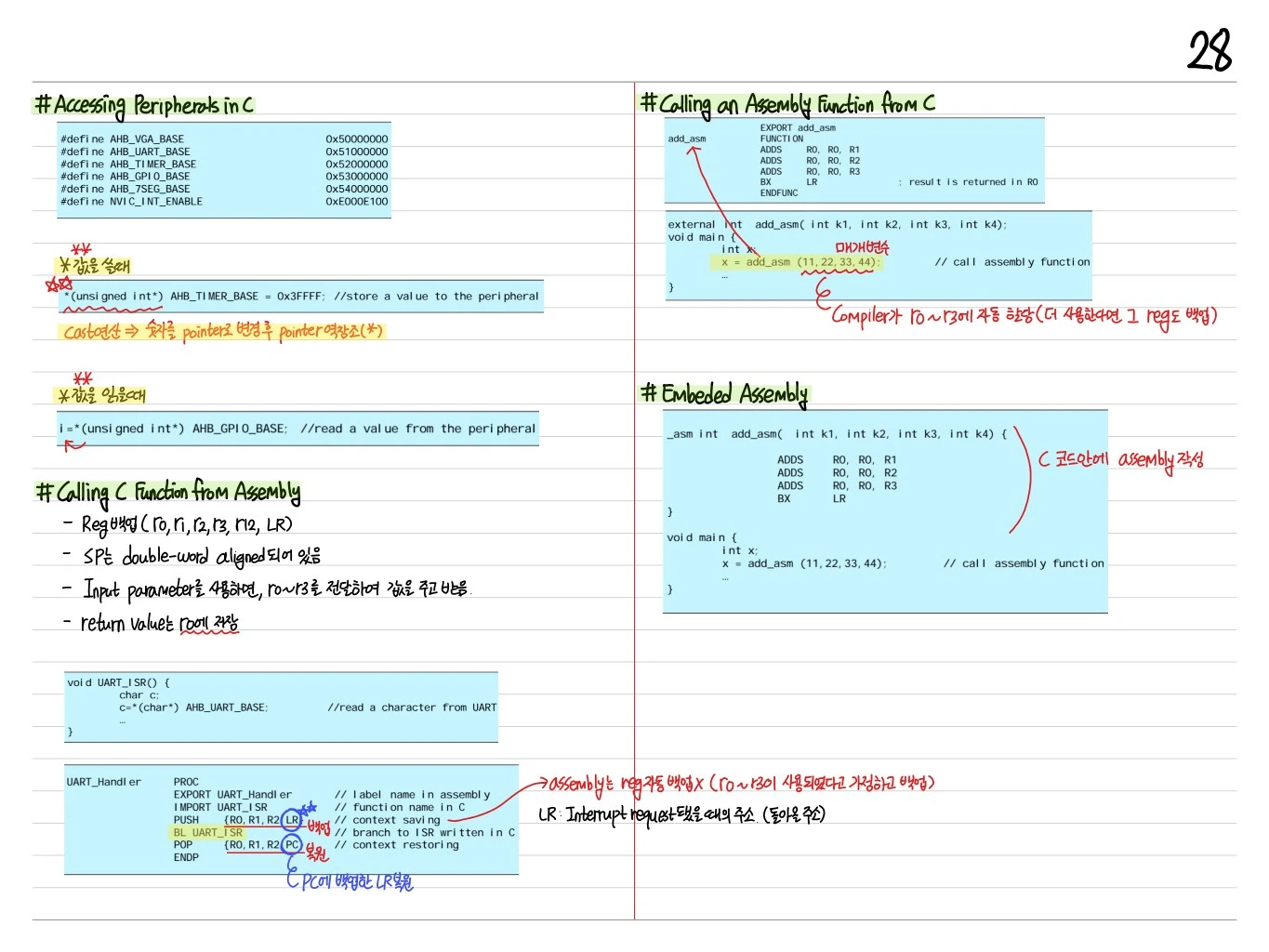
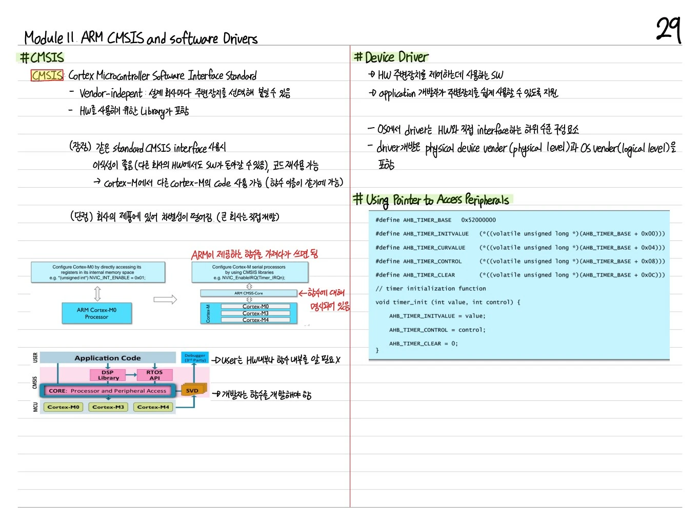
ARM 표준 SW interface:
- Core peripheral access (NVIC, SysTick, SCB)
- Vendor-specific register definitions
- DSP, NN library (option)
예:
#include "stm32f10x.h"    // CMSIS device header

int main(void) {
    RCC->APB2ENR |= RCC_APB2ENR_IOPCEN;   // GPIOC clock enable
    GPIOC->CRH = 0x00300000;              // PC13 output

    while (1) {
        GPIOC->ODR ^= (1 << 13);          // toggle LED
        for (volatile int i = 0; i < 100000; i++);  // delay
    }
}
Interrupt Handler
CMSIS는 vector table을 자동 생성. Handler를 작성만 하면 연결:
void TIM2_IRQHandler(void) {
    if (TIM2->SR & TIM_SR_UIF) {
        TIM2->SR = ~TIM_SR_UIF;    // clear flag
        GPIOC->ODR ^= (1 << 13);   // toggle LED
    }
}
Linker script에서 TIM2_IRQHandler의 주소가 vector table의 해당 offset에 등록됨.
Clock 설정
SoC의 clock 시스템은 복잡 (HSI, HSE, PLL, AHB/APB prescaler).
void SystemInit(void) {
    // Enable HSE
    RCC->CR |= RCC_CR_HSEON;
    while (!(RCC->CR & RCC_CR_HSERDY));

    // Configure PLL
    RCC->CFGR = RCC_CFGR_PLLSRC | RCC_CFGR_PLLMULL9;
    RCC->CR |= RCC_CR_PLLON;
    while (!(RCC->CR & RCC_CR_PLLRDY));

    // Switch SYSCLK to PLL
    RCC->CFGR |= RCC_CFGR_SW_PLL;
}
Debugging Tools
- printf via UART:
syscalls.c에서_write()재정의 - Semihosting: ARM debugger를 통해 stdout
- SWD (Serial Wire Debug): breakpoint, watchpoint, live register view
- ITM (Instrumentation Trace Macrocell): 고속 trace
최적화 Tips
- Inline: 짧은 함수는
static inline으로 - volatile은 꼭 필요한 곳에만 (최적화 방해)
- Cache alignment: DMA buffer는 cache line에 정렬
- -O2 / -Os: gcc 최적화 레벨, 임베디드는 크기 중요
정리
| 개념 | 핵심 |
|---|---|
| Memory-mapped I/O | Peripheral = 주소 |
| volatile | Compiler 최적화 방지 |
| Struct 접근 | Register group 추상화 |
| Bit op | Set/Clear/Toggle/Check |
| Startup | Vector table → Reset handler → main |
| Linker script | FLASH/RAM layout 정의 |
| CMSIS | ARM 표준 SW interface |
| Interrupt handler | C 함수 + Linker 연결 |
C로 SoC 프로그래밍은 hardware level을 C pointer로 추상화하는 작업. volatile, struct, bit op를 숙달하면 어떤 MCU도 직접 제어할 수 있다.
 SoC Note
 AI Study Note
 Embedded Note
Comments (0)
No comments yet. Be the first to comment!
Please to write a comment.